
So in my last couple of posts I promised I’d get into something more technical, more about what I’m actually doing rather than just where my head’s at. Here we go.
I’ve had these little hexagonal devices sitting around for a long time. They’re conference badges with the ring of LEDs on them, a couple of buttons, and an ESP32 chip inside. Open source hardware, designed by a company called Tekt Industries. And for years I never really found a use for them, because I didn’t have the original firmware source code. Without that I couldn’t tell what the hardware was actually doing, so I couldn’t make it do anything of my own.
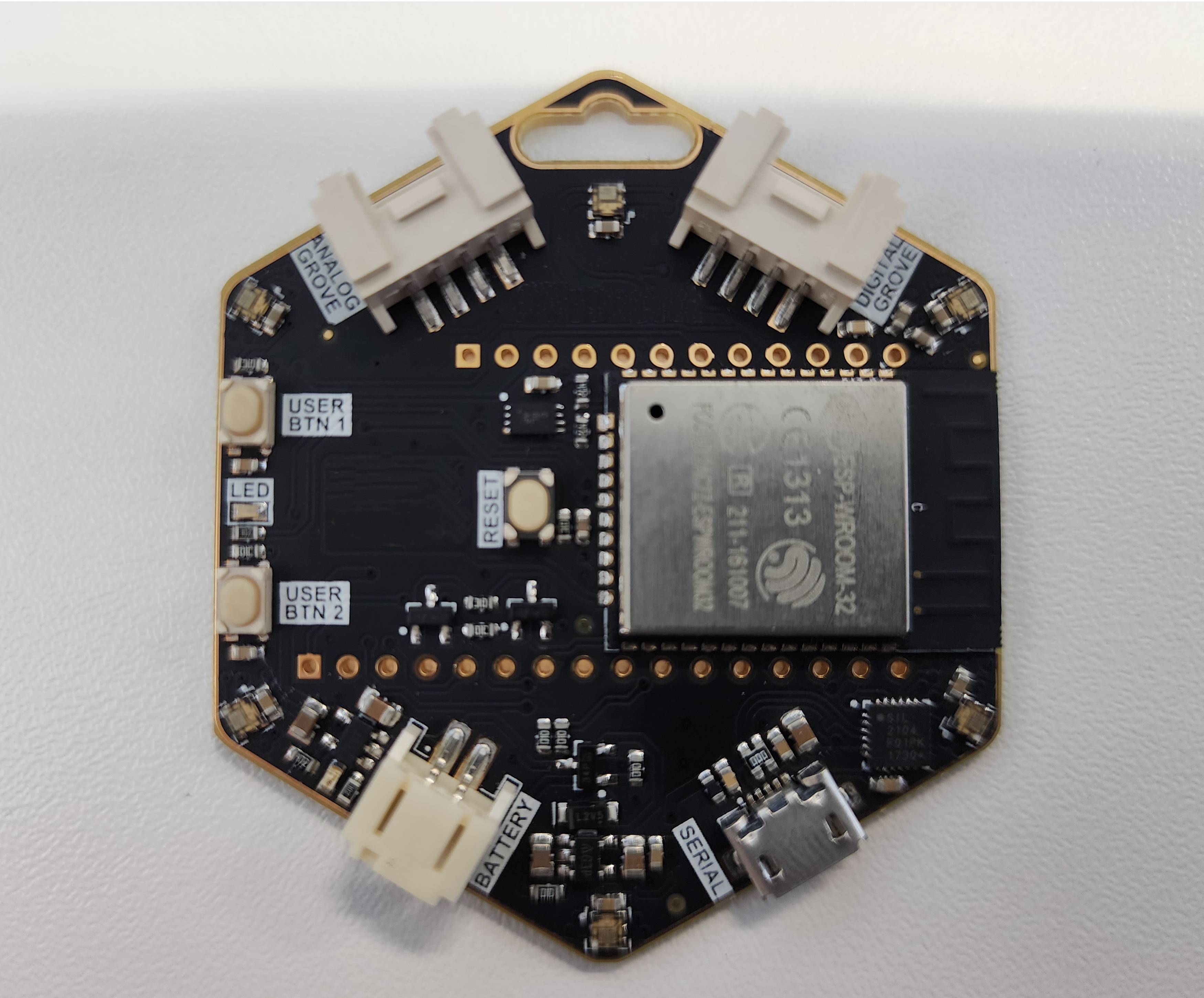
I’d had a few goes at it over the years. I spent a lot of time learning how to dump firmware off a chip, how to carve the existing programs back out of a flash image, trying to read what it was doing with the hardware. But it was always a side thing I’d pick up and put down, and I could never spend enough time on it in one go to get to the actual detail I needed, it was a steep learning curve for me. So it ended up just sitting in my locker.
This time was different, because I did it with an AI agent sitting next to me the whole way. And honestly it’s exactly the kind of thing I was talking about in the earlier posts, where AI has re-sparked my curiosity. The way I worked with it is kind of the point of the story.
Starting with what I didn’t know
The thing I actually wanted was the LED ring. If I could drive the ring, I could make the badge mine. But I was a long way from that. All I had was a sealed device, no source, no documentation, and the only way through was to understand it first.
So I plugged a badge into the laptop and told the AI what little I knew: it was connected over USB, and it was an ESP32 of some kind. From there we worked it out together. It walked the device over the serial connection, dumped the flash, and started pulling the image apart, reading the strings and the layout back to me as it went. The dump-and-extract part was familiar from my earlier attempts, but having something that could grind through the slow parts quickly, and explain what it was seeing, meant we got further in an afternoon than I’d ever managed on my own.
What came back was a clear picture of the hardware. The chip is an ESP32-WROOM-32 module, with 4MB of flash and crucially no flash encryption, which is the whole reason dumping it worked at all. On the back there’s a Silicon Labs CP2104 USB-to-UART bridge, which is what allowed talking to it over the micro-USB port. And the flash itself carried a standard ESP32 partition table, so once it was dumped we could read the layout straight off: an NVS partition for config, two OTA app slots, and a couple of SPIFFS filesystem partitions holding a Mongoose OS app. There were three badges in the drawer, and it turned out one was a decoy running a stock demo and another was running the real conference app.
That’s the moment a reverse-engineering job stops being a 4MB blob and starts being a device you understand. But understanding what was on it still wasn’t the same as controlling the LED ring, and the ring was the part that had always beaten me.
Giving the agent eyes
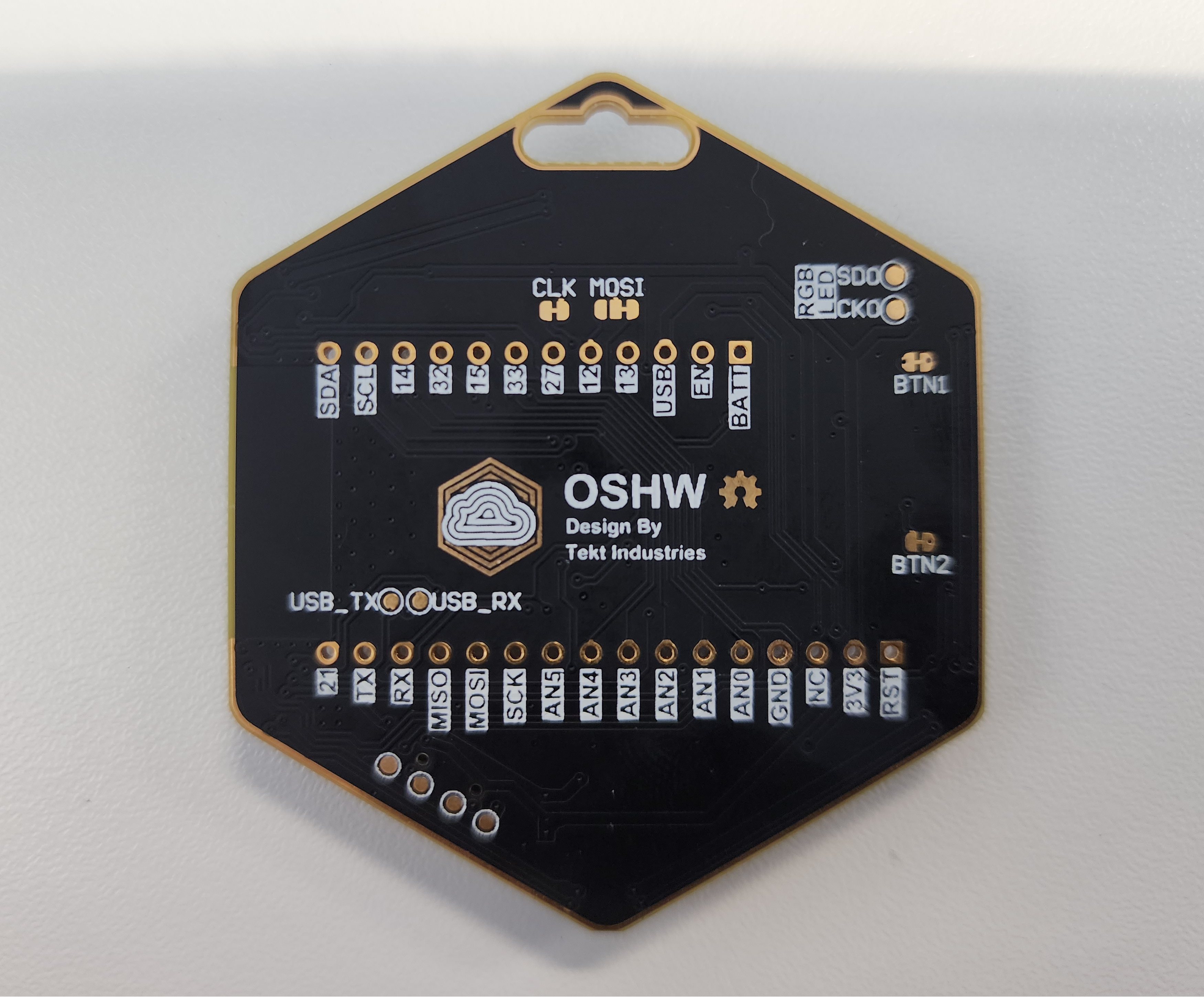
Before we could go pin-hunting, the agent had a basic handicap I had to deal with: it couldn’t see the thing. And one of the bigger steps, one I didn’t expect to matter as much as it did, was simply fixing that. I took photos of the device, front and back, close up, and handed them over.
Think about it from the agent’s side. It can read firmware, it can run tools, it can reason about pins all day long, but it genuinely cannot see the thing sitting on my desk. The moment I gave it clear pictures of the board, front and back, it could suddenly reason about the physical layout. It went from working blind to actually having a picture of what we were dealing with.
And it did more than just look. It actually read the text off the board. The silkscreen labels, the little printed markings next to the connectors and the chip, the writing you’d normally squint at under a magnifier. It OCR’d those straight out of the photos and used them to make much more educated guesses about how the thing worked. Picking out that a connector was labelled as a Grove port, or identifying the chip and module from the text printed on them, meant its guesses about which pins did what were grounded in what the manufacturer had actually written on the board, not just pattern-matching on shapes. That narrowed the search down a lot before I ever picked up a multimeter.
But I want to be honest about the limit. You can’t read a buried trace through a photo. The photos were a brilliant way to orient the agent, to let it understand the shape of the problem and read the maker’s own labels instead of me describing everything in words. What they couldn’t do was tell us the one thing I actually needed.
The bit that nearly beat me
What I needed was the exact GPIO pins the LED ring was wired to, and that was where the photos ran out of road. The pins aren’t labelled, and the traces that would answer it disappear under the chip module and through inner layers of the board. So the educated guesses stayed guesses, and I spent a long time making them and being wrong, repeatedly.
The first thing we got wrong was what kind of LED these even were. The agent assumed a WS2812, the common NeoPixel type, which is a single-wire part where all the colour data goes down one line with timing so tight that a stray interrupt corrupts it. We spent real effort chasing a single data pin on that assumption, and part of why the early sweeps were so unreliable is that a WS2812-style bit-bang gets wrecked by Wi-Fi and Bluetooth interrupts firing in the background. It turned out these aren’t WS2812 at all, they’re APA102, also known as DotStar, which is a two-wire part: a data line and a separate clock line. That one distinction changed everything, because a clocked part is far more forgiving of timing, but it also meant I was now hunting for two pins that had to work together, not one.
And it wasn’t just the pins and the protocol it got wrong. At one point it inferred the ring had somewhere between 12 and 24 LEDs, because that’s a common size for an addressable ring. In reality the badge is a hexagon with a single LED at each point, so six, full stop. That’s the sort of thing I could see at a glance and it couldn’t, and if I hadn’t corrected it we’d have been chasing a ring twice the size of the real one. There were a few of those moments where I had to step in and set it straight from the physical reality in front of me.
So we tried everything that didn’t involve just brute-forcing it. Reasoning from the labels in the photos. Guessing the standard SPI pins the chip would normally use. Probing pads with a multimeter to chase continuity. All of it dead-ended. At one point the agent confidently told me it had found the pins, and it was wrong, because it had inferred the answer from timing in a log file instead of actually confirming it. I had to pull it up on that. More than once, actually. It kept wanting to move fast and tell me things had changed before I’d confirmed they had, and I’m the one with eyes on the actual device, so I made it slow down and do strictly one thing at a time and wait for me to tell it what the ring was really doing.
That’s a lesson that applies way beyond this badge. The AI is fast and it’s useful, and the photos let it see the shape of the board and read the maker’s labels, but it still can’t watch the ring light up in real time. I could. So the right division of labour was it drives the probing and I’m the sensor. One step, I look, I report, next step. And once we accepted that was the only honest way to find these pins, the method almost picked itself.
How we actually cracked it
The approach that finally worked was brute force, but the honest word for it is methodical. Because APA102 needs a data pin and a clock pin working as a pair, the search space was every plausible combination of two pins. We flashed a little program onto the badge that marched through every plausible pair, one pair at a time, lighting the ring on each pair while I watched for the moment it went green. Compiled C, not an interpreted script, and the radios switched off, so the signal timing was clean and nothing in the background could corrupt it. We only ever changed one thing between steps: hold the clock pin fixed, move the data pin on by one, look, report, repeat. It was tedious, no way around that, but changing a single variable at a time is exactly what made it work. Each step either ruled something out or pointed at the answer, with no ambiguity about which change caused what.
What really unlocked it was reading the failure, not just waiting for success. On one pair the ring lit three of the six LEDs a steady white, and it stayed exactly like that no matter which data pin I tried next. That non-change was the clue. In a clocked protocol like APA102, a correct clock pin will shift whatever’s on the data line into the LEDs even if the data is garbage, so a steady partial pattern that doesn’t react to changing the data pin means the clock is right and the data pin still isn’t found. So I pinned the clock and swept only the data pin from there. Three LEDs stuck white, same three white, same three white again, and then all six green.
That was it. Data on GPIO16, clock on GPIO14. An APA102 ring, six LEDs, with the colour bytes in blue-green-red order rather than the usual red-green-blue. Each LED frame is a brightness header byte followed by those three colour bytes, bookended by a start frame of zeros and an end latch of clock pulses. After all the dead ends, it was almost anticlimactic.
The buttons went the same way. One was easy, the stock firmware had already told us the first button sat on GPIO32, but the second was a complete unknown, so we reached for the same trick. Flashed a scanner that printed the state of every candidate pin each cycle, I held the button down, and one pin flipped from high to low. GPIO33, wired active-low with an internal pull-up, exactly the same as the first. The only confusion was that three of the input-only pins float low at rest, so I had to ignore those and watch for the pin that actually changed on the press. Same pattern as the ring: let the device tell us the truth one controlled step at a time, instead of guessing.
Making it mine
With the pins known, everything after was the fun part, the part I’d been waiting years to get to. I’ve now got a program on all three badges where one button cycles through solid colours and a rainbow animation then an off mode, and the other button cycles brightness. It’s built in C on PlatformIO with the Arduino framework, which is a far nicer place to work than the Mongoose JavaScript the badges shipped with.

A few details I’m quietly pleased with. The ring driver is a from-scratch bit-bang of the APA102 protocol, no library needed, just toggling the data and clock pins by hand, which works fine precisely because APA102 is clocked and forgiving. Brightness isn’t done by scaling the colour values, it rides on the APA102’s own five-bit per-LED brightness field, so I get real dimming without losing colour resolution, cycled through four levels on the second button. Both buttons are properly debounced so one press is one step, not a jittery double. And the current mode and brightness get written to the ESP32’s NVS, its little non-volatile key-value store, but only on a button press rather than every animation frame, so it remembers what it was set to across a power cycle without wearing out the flash. Little thing, but it’s just a nice bit of polish.
I was also careful not to burn any bridges. I kept verified backups of the original firmware on every device, full 4MB images with their hashes checked, so I can always put them back exactly how they were.
And because I know how these projects go, I wrote myself a proper development guide for the badge while it was all still fresh. The ring, the buttons, Wi-Fi (which I had working previously), Bluetooth, the Grove connectors, even what battery it’d need. So the next time I want to build something on these, I’m not starting from zero. Future me will thank present me for that.
Why this one mattered to me
Before the sentiment, the thing that really stuck with me was the sheer speed of it. I’d had these badges for years, and across several attempts I’d only ever learned the dump-and-extract side without getting near the answer. This time, start to finish, it took about four or five hours to go from a sealed black box to full control of the LEDs. The same problem that had beaten me across all those earlier attempts fell over in a single afternoon.
And the way that landed was important. For a while I felt like the hands-on technical work had drifted away from me, that my job had become advisory and strategy and I’d lost the spark. This was me getting my hands dirty again, on my own terms, for no reason other than I wanted to.
And the AI didn’t replace the fun of it. It took the slow, repetitive, easy-to-get-wrong work off my plate, the flashing and the sweeping and the log capturing, and it kept good notes so I didn’t have to hold it all in my head. That’s why it was fast. But the judgement was mine. Knowing when it was confidently wrong, knowing to slow it down, being the one who could actually look at the ring, that was all me. Starting small, breaking the problem into steps, validating what the tool hands back. Same lessons I wrote about with AI generally, just applied to a stubborn little badge with a ring of LEDs.
More technical ones to come. I think I’m having some fun again.